


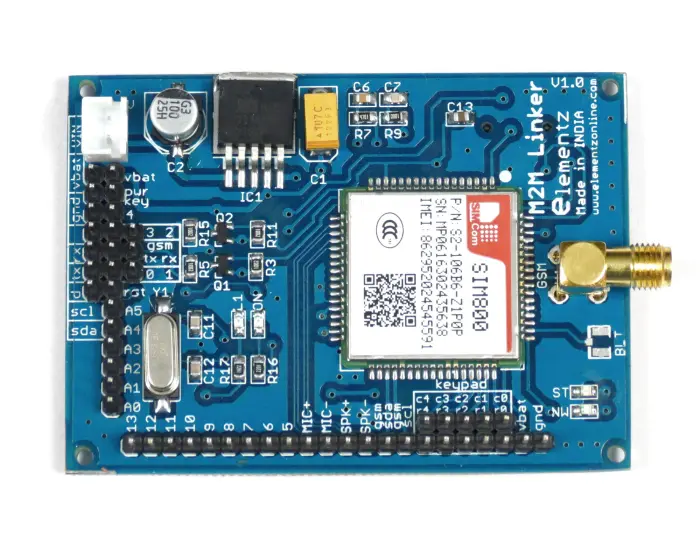
The M2M Linker features an ATmega328 and SIM800 which provides the flexibility of arduino along with the added features of SIM800 which has GSM and GPRS functionality.SIM800 is a complete Quad-band GSM/GPRS solution in a SMT type which can be embedded in the customer applications.
FEATURES
- Arduino Compatible.
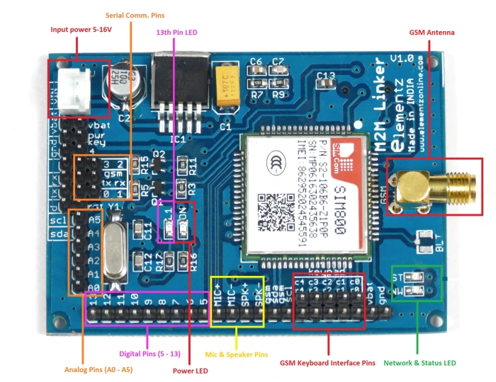
- It have multiple analog & digital pins like Arduino
- Its like an Arduino with integrated GSM/GPRS support
- Quad-band 850/900/1800/1900MHz
- GPRS multi-slot class12 connectivity: max. 85.6kbps(down-load/up-load)
- GPRS mobile station class B
- Controlled by AT Command (3GPP TS 27.007, 27.005 and SIMCOM enhanced AT Commands)
- Supports Real Time Clock
- Supply voltage range 5V ~ 12V
- Supports 3.0V to 5.0V logic level
- Low power consumption, 1mA in sleep mode
- Standard SIM Card
POWERING THE MODULE
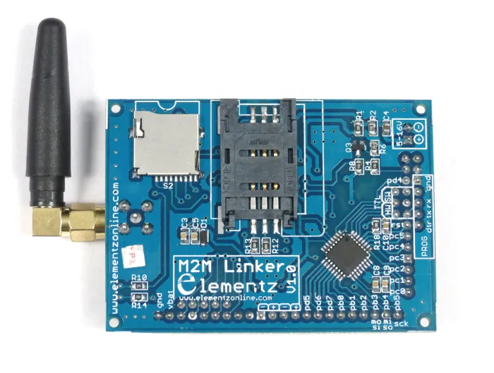
Firstly insert the SIM card in the sim holder. Make sure to use a normal SIM card (Micro or nano SIM cards can be used with the help of sim card adapter.)
You can power the board from a power adapter(9V/12V – 1A).
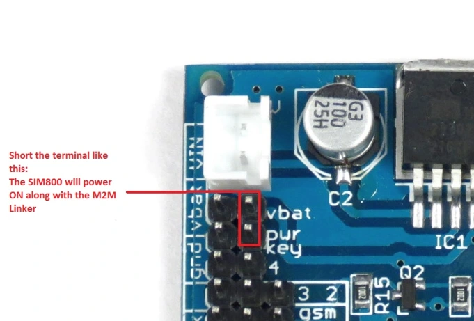
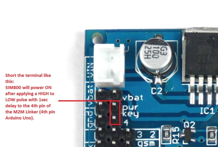
Hardware Power On:
Short the terminals by using jumpers. Now the SIM800 will power ON along with the M2M Linker.
Software Power On:
Short the terminals by using jumpers. Now the SIM800 will power ON only after applying a HIGH to LOW pulse with 1sec delay to the 4th pin of the M2M Linker (4th pin – Arduino Uno).
M2M LINKER BOOT LOADING
For boot loading the M2M linker, select the programmer as Arduino as ISP.And select the board as Arduino as UNO.Then select the example from files then uploading the code.
- Select the Arduino UNO as Board from the,tools Select the Arduino UNO as Board from the Tools –> Board –> Arduino UNO.
- Tools –>Programmer–>Arduino as ISP.
- Files –>examples –>Arduino ISP.
- Uploading the code.
Connections:
- Vbat and powerkey short
- Connect the VCC of Arduino to the VCC of M2M Linker.
- Connect the GND of Arduino to the GND of M2M Linker.
- Connect the MOSI(11)pin of Arduino to the MOSI(11)pin of M2M Linker.
- Connect the MISO(12)pin of Arduino to the MISO(12)pin of M2M Linker.
- Connect the SCK(13)pin of Arduino to the SCK(13)pin of M2M Linker.
- Connect the Arduino pin 10 to the M2M Linker RESET pin of M2M Linker.
For Boot Loading:
- File–>preference–>Additional board manager URL
https://mcudude.github.io/MiniCore/package_MCUdude_MiniCore_index.json
copy and paste the link after a comma. - Then download from Board manager(Board→Board manager).
- Tools→Board→select IC name.
- Tools→Burn Boot Loader.
- Then Tools Burn Boot loader.
Programming the Board
The board has an Atmega328 based on the Arduino UNO. You can program it using Arduino IDE.Select the Arduino UNO as Board from the Tools–> Board –> Arduino UNO.Now you need a FTDI/CP2102 USB to UART converter/adapter to program the board. Connect it to the computer. Select the COM port. Connect the RX of the USB to UART converter to the Hardware TX of the board and vice versa. Connect VCC and GND. Connect DTR of the converter to DTR of the board. Now you are all set.
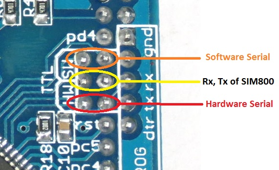
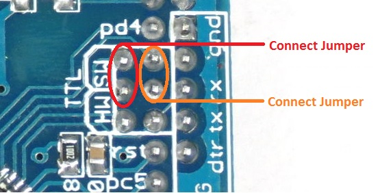
Hardware Serial
Short the terminals by using jumpers. Now the UART of SIM800 and ATmega328 are connected. Now the MCU and GSM will communicate via UART (Hardware Serial).
Software Serial
Short the terminals by using jumpers. Now the UART of SIM800 is connected to the Software Serial pins (3 & 2) of ATmega328. Now the MCU and GSM will communicate via Software Serial pins of Atmega328.
If you want to use only the SIM800 functionalities, you can do so by connecting to the Rx and Tx pins of the SIM800 on the board.

