


Hello enthusiasts,
In this post, I am throwing some light into introducing LCD Serial Interface Board ,familiarising you with its major AT commands used to communicate with this board. Along with this, the steps to interface this board with a micro-controller or Serial to USB converter will be depicted as well.
LCD Serial Interface Board concatenates a 16x2 LCD screen controlled easily by AT (Attention) commands. It is operated through simple SERIAL communication in ASCII format and can easily be interfaced with a microcontroller imparted with UART pins. The module is already incorporated with an Atmega 8 micro-controller ,which could memorize the data written previously, even after a power shut down.
Features:
- Two power supply input provisions. One of 12V supply provision via dc jack and another of 5V provision through pin header.
- UART serial communication for sending data to display. Communication Parameters:- baud rate: 9600, 1 Start bit,8 Data bits, 1 Stop bit, No Parity.
- All setups are saved in memory. Once setup, no need to re-setup after power failure.
- Contrast adjustment of LCD possible.
Pin Description:
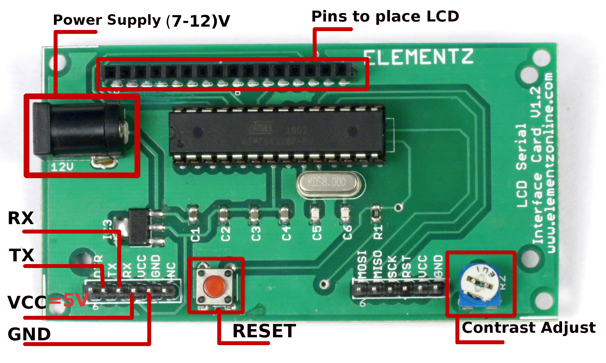
Figure 1:Pin Layout LCD Serial Interface Board
Figure 1 displays the pin layout for LCD Serial Interface board.
|
Pin Name |
Pin Description |
|
VCC |
Power Supply (5V only) through pin headers |
|
TX |
Transmitter pin : can be connected to receiver pin of micro-controller/CP2102 to allow data to be transmitted out |
|
RX |
Receiver pin : can be connected to transmitter pin of micro-controller/CP2102 to allow data to be received in |
|
RESET |
Pressing this button resets the micro-controller in the LCD Serial Interface board , so that the code uploaded on it starts running from the beginning. Hence, board starts displaying from the welcome note (if it is enabled) by default. |
|
Contrast Adjust |
By turning this potentiometer, the screen contrast of the LCD can be controlled |
|
GND |
Ground |
TABLE 1: Pin Layout & description
|
Sl No: |
AT command |
Description |
Usage |
|
1 |
AT+DATA=<Line Index>,<Address>,<Data to be printed> |
Writes data into LCD.
values taken:either 1 or 2. 1- Row 1 2- Row 2 Invalid values return an “INDEX ERROR” message
values taken: 00 to 15. 00 - starting position of data display from zeroth column. 15 - starting position of data display from column 15/last column. All invalid values return an “ADDRESS ERROR” message.
|
AT+DATA=1,02,Hello how are you
Here data “Hello how are you” is written to line 1 or first row starting from column position 2 |
|
2 |
AT+CLEAR=<Input> |
To clear data.
values taken:0,1 or 2. 0- to clear both rows. 1- to clear the first row, 2- to clear the second row, Invalid input returns an “INPUT ERROR” message. |
AT+CLEAR=1
Clears all data in first row |
|
3 |
AT+SCROLL=<Input> |
Sets for left scroll,right scroll or no scroll.
values taken: 0,1 or 2 0 -for no scroll. 1 -for left scrolling, 2 -for right scrolling Invalid input returns an “INPUT ERROR” message. Default value:0 ,for no scroll |
AT+SCROLL=1
Scrolls all data to the left completely. |
|
4 |
AT+DIR=<Input> |
To change the direction of error message.
values taken:0,1 or 2 0 - displaying in the serial monitor only, 1 - displaying in the LCD display only 2 - displaying in both serial and LCD displays. Invalid input returns an “INPUT ERROR” message. Default value:0 ,displays error message in serial monitor |
AT+DIR=0
Here, error messages are displayed in serial monitor only |
|
5 |
AT+ECHO=<Input> |
To enable or disable echo( act of printing typed out text into serial monitor)
values taken: 0 or 1 0- disables echo 1- enables echo Invalid input returns an “INPUT ERROR” message. Default value:1 ,echo enabled |
AT+ECHO=0
Here,typed out text will stop getting displayed in serial monitor |
|
6 |
AT+WEL=<Input> |
To enable or disable welcome note Input: Used to enable or disable welcome note. values taken: 0 or 1 0- disables welcome note 1- enables welcome note Invalid input returns an “INPUT ERROR” message Default value: 1 ,welcome note enabled |
AT+WEL=0
Here, welcome note at the beginning will be disabled from displaying |
TABLE 2: LCD Serial Interface Board AT commands & description
Table 2 entails the major AT commands used to communicate with LCD serial interface board.
Note 1:Send “Enter” character or type 0x0D (hex code for “carriage return” ) in program at the end of each AT command.
Note 2: Ensure sufficient delay between each AT command used. Minimum advised delay is 1 sec.
Note 3:LCD serial interface board can be connected to CP2102 or micro-controller with a baud rate of 9600.
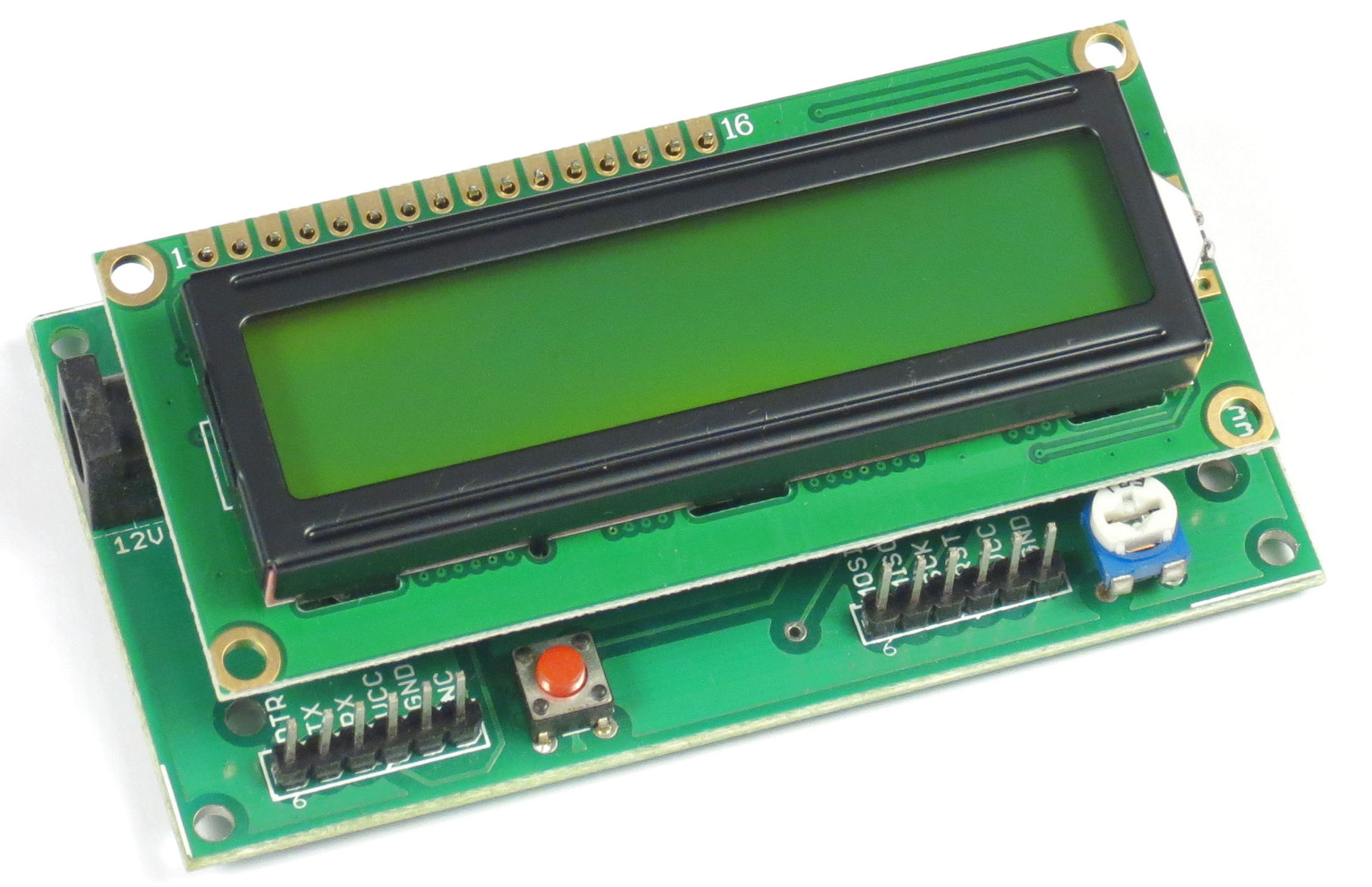
Figure 2:16x2 LCD on LCD Serial Interface Board
So you might have familiarised well with the pin connections and AT commands. Now, we can go for the hardware connections and programming.
In this part of the post, I am going to provide you insights on the pin connections regarding LCD Serial Interface board with serial to USB converter or a micro-controller.
Hardware Prerequisite:
- LCD Serial Interface Board. It is readily available from our online Store.
- 16x2 LCD. (Purchase from our Store).
- Serial to TTL or CP2102.(Available on our Store as well) or Arduino UNO board (buy online from our Store)/ATmega microcontroller(online Store).
- 12V power adapter (online Store ).
- Jumper wires.
Step by Step instructions to connect CP2102/microcontroller to LCD Serial Interface Board:
STEP 1:Connect dc jack of LCD serial interface board to power supply adapter or provide VCC pin of board with 5V power supply using jumper wires.
STEP 2:Connect TX of LCD serial board with RX(receiver pin) of micro-controller/CP2102 and vice-versa.
STEP 3:Connect GND of LCD serial board with ground of micro-controller/CP2102. For the sake of depiction, Figure 3 has been presented with pin connections between LCD serial interface board and CP2102(You can definitely replace CP2102 with a micro-controller, in case you want, since the pin connections with LCD serial interface board is essentially the same).
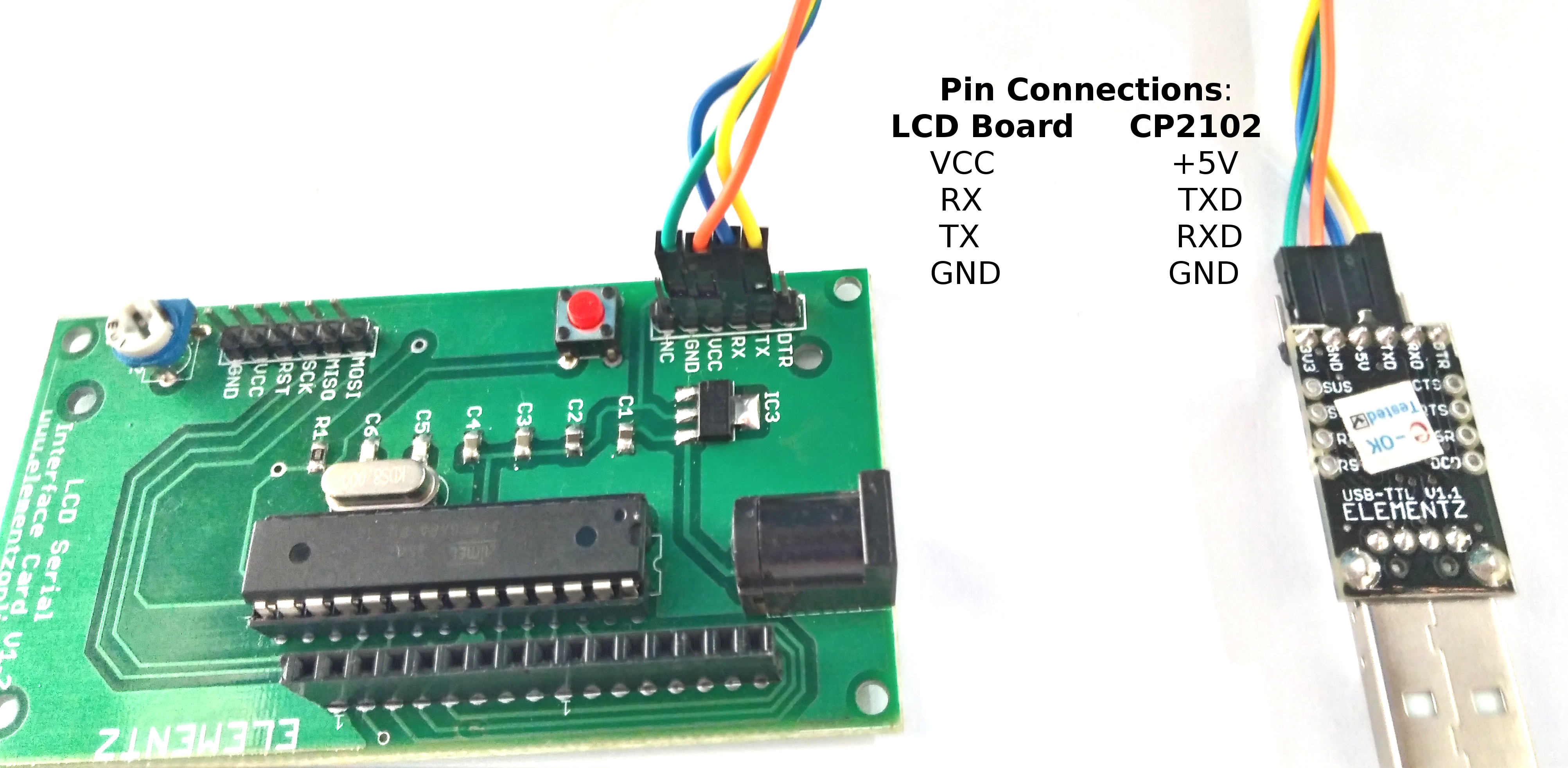
Figure 3:Pin connections between LCD Serial Interface Board & CP2102
STEP 4:Open serial terminal console to type in AT commands or send data serially to LCD serial interface board using micro-controller programs with a baud rate of 9600.
Sample Micro-controller Program using AVR to communicate with LCD Serial Interface Board:
//------------------------------------------------------------------------------
/*sample code for printing a data using Elementz LCD Interface Board written by Elementz Engineers Guild Pvt Ltd (No copyright restrictions).The code is written in AVR studio and the crystal frequqency is 8 Mhz.*/
//------------------------------------------------------------------------------
#include <avr/io.h>
#include <util/delay.h>
#include <avr/interrupt.h>
#include <string.h>
//Functions defined for initiating the uart and processing the data received and the data to be transmitted.
void init_usart(unsigned int baud)
{
UCSRA=(0x00);
UCSRB=0x98;
UCSRC=0x86;
UBRRH=baud>>8; //baud value is 51 for a baudrate of 9600
UBRRL=baud;
}
void usart_putchar(char data)
{
while(!(UCSRA & 0x20));
//Now write the data to UART buffer
UDR=data;
}
void print_uart(char *buffer)
{
int i;
for (i=0;buffer[i] != '\0' ;i++)
usart_putchar(buffer[i]);
usart_putchar(0x0D);
//usart_putchar(0x0A);
}
//-------------------------------------------------------------------
/*main code starts here.*/
int main(void)
{
init_usart(51); //initiating UART
_delay_ms(2000);
while(1)
{
_delay_ms(2000);
print_uart("AT+CLEAR=0");
_delay_ms(3000);
print_uart("AT+DATA=1,00,Hi World");
_delay_ms(500);
print_uart("AT+DATA=2,00,i am back");
}
return 0;
}
Sample Micro-controller Program for Arduino:
/* Author: Elementz Engineers Guild Pvt. Ltd (No copy right restrictions)(www.elementzonline.com) */
void setup()
{
Serial.begin(9600);//initialising serial communication
}
void loop()
{
Serial.print("AT+CLEAR=0\r");
delay(3000);
Serial.print("AT+DATA=1,00,Hi World\r");
delay(1000);
Serial.print("AT+DATA=2,05,I am Back\r");
delay(3000);
while(1)
{
Serial.print("AT+SCROLL=1\r");//for left scrolling
delay(5000);
Serial.print("AT+SCROLL=2\r");//for right scrolling
delay(5000);
Serial.print("AT+SCROLL=0\r");//for stop scrolling
delay(5000);
}
}
")
")


")
")