


Skytraq S1216F8-GI3 GPS/GNSS/IRNSS/NAVIC/GAGAN Break Out Board Module is a Breakout Board having satellite navigation receiver, capable of supporting band L5-NavIC (India) and L1-GAGAN/GPS/GLONASS signals to provide 3D navigation. It has optional mounting of IMU sensors for Dead Reckoning applications and can also support optional RTK module. SkyTraQ chipset combined with best board level RF design of BOB and matched antenna, offers superior cold start sensitivity that allows to acquire, track, and get position fix autonomously even in difficult and weak signal environments.
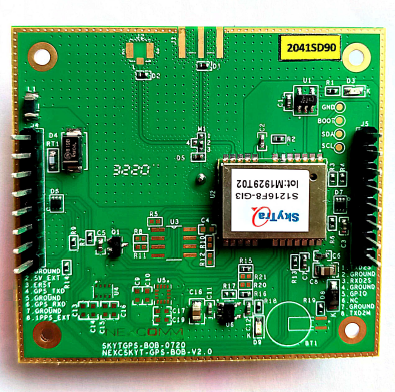
The S1216F8‐GI3 is a satellite navigation receiver capable of using L5 NavIC, L1 GAGAN/GPS/GLONASS signal to provide 3D navigation in a single compact SMD module. The S1216F8‐GI3 has 56 tracking channels and could track all in‐view satellites. It is fully autonomous such that once power is applied, the receiver automatically searches, acquires, and tracks satellite signals. When a sufficient number of satellites are tracked with valid measurements, the receiver produces 3D position and velocity outputs.
NavIC + GPS/GLONASS triple‐satellite capability enables using a greater number of satellite signals than GPS‐only receivers. The increased satellite number offers superior performance in challenging urban canyon and multipath environments.
The S1216F8‐GI3 module contains SkyTraq Venus 8 positioning engine inside, featuring high sensitivity, low power consumption, and fast TTFF. The superior cold start sensitivity allows it to acquire, track, and get position fix autonomously in a difficult weak signal environment. The receiver’s superior tracking sensitivity allows continuous position coverage in nearly all outdoor application environments. The high-performance signal parameter search engine is capable of testing 16 million time‐frequency hypotheses per second, offering superior signal acquisition and TTFF speed.
Features of SkyTraQ GNSS Receiver chipset
- L1, L5 signal reception to support GPS and NavIC. Works with NavIC, GAGAN, GLONASS, GPS satellites and more. Support for AGPS
- Support for Automotive Dead Reckoning (ADR), Odometer-less Dead Reckoning (ODR) with either built-in sensors within the GNSS BOB or with external sensors
- Optional Real-time Kinematic (RTK) module for Centimetre level precision and accuracy
Chip Features
- L1 / L5 signal reception
- Works with NavIC, GAGAN, GPS, GLONASS
- Less than 30-second cold start TTFF
- ~1-second hot start
- ~2.5m CEP accuracy
- Multipath detection and suppression
- Works with passive and active antenna
- Complete receiver in 12mm x 16mm size
- Operating temperature ‐40 ~ +85oC
- Pb‐free RoHS compliant
Benefits
- Proper ground plane and RF layout design
- Suitable on board or external antennas for best overall system performance
- Possibility to use any external antenna with antenna matching option
- One BOB suitable for multiple requirements (GPS, NavIC, ODR, RTK)
Applications
- Navigation and asset tracking
- Timing reference
Powering the module
1. Power the module either using 5v 2A adapter externally using power supply board or by connecting CP2102 usb to ttl directly for getting the gps information like latitude, longitude, speed, time, data, etc.
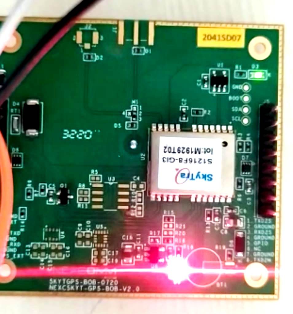
The power led (red) will be ON which indicates the module got its power required for the operation.
2. It will take some time to get the current position of the GPS location. When GPS acquires the exact location you can see the blue led is blinking.
Connecting with CP2102 USB to UART Serial Converter
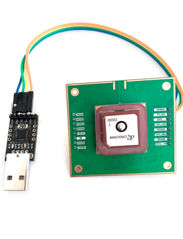
- 5V_EXT of SkyTraq → 5V of TTL
- GPS_RXD of SkyTraq → Tx of TTL
- GPS_TXD of SkyTraq → Rx of TTL
- GND of SkyTraq → GND of TTL
Connect the usb to ttl to the usb port of the pc.
Using the test utility
The steps required for testing the module to the PC is shown below:
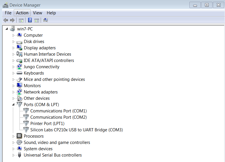
- Open the device manager and check the PORTS .You can see the com port to which you are connected
Here you can see its COM3.
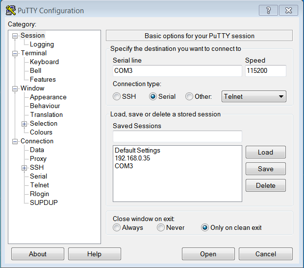
- Open the terminal PuTTY ,for communicating with the serial port.
The baud rate is 115200.
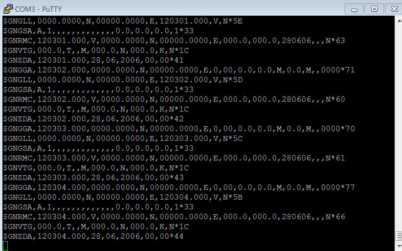
- The data you are getting over a serial interface are actually NMEA sentences.
NMEA is an acronym for the National Marine Electronics Association. This is a standard message format for Nearly all GPS receivers.
- When GPS is not in range, RMC data is unavailabale in the puTTy terminal.
RMC – Recommended Minimum Specific GNSS Data Time, date, position, course and speed data provided by a GNSS navigation receiver.
Format: $--RMC,hhmmss.sss,x,llll.lll,a,yyyyy.yyy,a,x.x,u.u,xxxxxx,,,v*hh
- It will take some time to get the current position of the GPS location. When GPS acquires the exact location you can see the green led is blinking.
- In the terminal you can see the updated RMC data of GPS module.
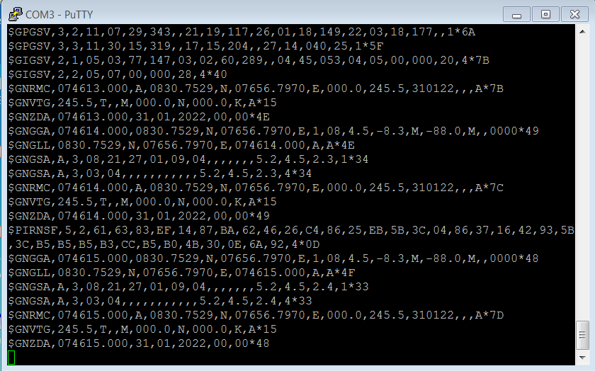
- $GNGSA – GPS DOP and active satellites
- $GPGSV – Detailed GPS satellite information
- $GNGLL – Geographic Latitude and Longitude
- $GNRMC – Essential GPS pvt (position, velocity, time) data
- $GNVTG – Velocity made good
GPS Visualise Softwares for GNSS Receiver data interpretation
- GPS Visualise software is useful for showing and interpreting the data from GNSS receivers in real-time. Most of the GNSS receivers provide data in NMEA standard format through a UART / Serial communication interface. The NMEA data format is human-readable and contains lots of information that will take some time to interpret with the NMEA standard documentation.
- In addition to the location information in latitude and longitude and altitude, the GPS Visualisation software can show the position of each satellite, the signal strengths from each satellite, and type of location fix (no fix, 2D fix, 3D fix ). Some softwares can even interact with the receivers to update the location data interval time, Assisted GPS ( AGPS ) function so that we can study and interact and make the most out of the GPS receiver we have for our projects. An additional benefit is that we can check the efficiency of different antennas and the impact of their mounting and orientation on tracking the satellites by comparing the number of satellites in view, the number of satellites which can be tracked in a given time, signal strength from each satellite. This will help us to choose the best antenna and fine-tune our receiver to reduce the Time to First Fix ( TTFF).
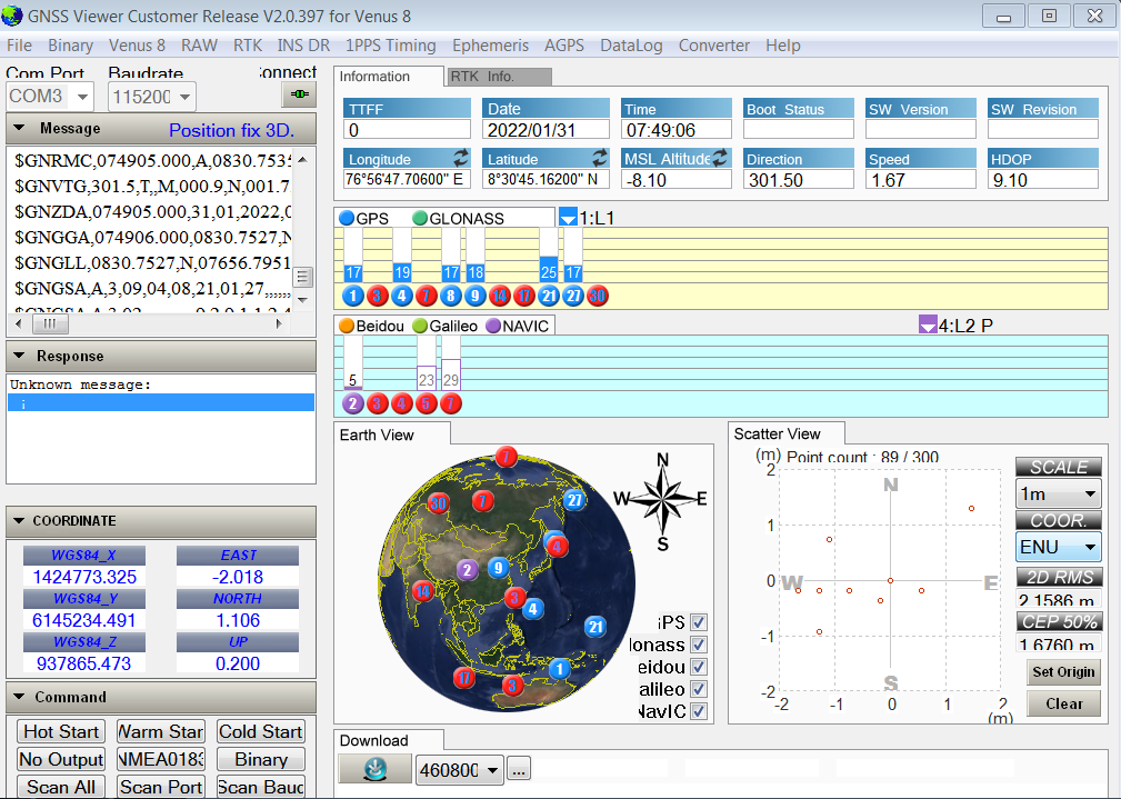
Navspark GNSS Viewer
- Originally made for Skytraq GNSS GPS receivers, but the GPS Visualisation using Navspark GNSS Viewer will work with other receivers which output NMEA data. In addition to the Satellite data visualization, the Navspark viewer can be used to experiment with the AGPS capabilities of Skytraq receiver modules which load the satellite ephemeris data into the ROM which will drastically improve the Time to First Fix ( TTFF ).
- After the position fix, the interface will show more options.