In the previous blog we discussed connecting ESP32 to the Google Cloud Platform (GCP). Now, In this tutorial we will learn how to establish a communication between two ESP32 boards connected to GCP. The tutorial consists of a ESP32 board connected with a DHT11 sensor, publishing data which is received by the second ESP32 board. A Cloud Function written in GCP acts as a bridge to facilitate the communication.


PINOUT


We will be using the built-in LED and push button of the ESP32 module for this tutorial with a DHT11 sensor monitoring the temperature and humidity.


HARDWARE CONNECTION


ESP32

DHT11

3V3

VCC

GND

GND

D15

Data


The second ESP32 board has no external peripherals connected as only the built-in LED is used in this tutorial.


GOOGLE IOT CORE ESP32 SETUP


Follow the previous blog for set up instructions. The link is given below:


https://www.elementzonline.com/blog/Connecting-ESP32-to-Google-Cloud-IoT


If you have already completed the setup, you can continue to the next step.


WRITING THE CLOUD FUNCTION


  • First open the GCP console

  • Now, navigate to the Cloud Functions page. (You can use the search tool)

  • Click the Create Function button.

  • Now fill in a preferred function name (Eg: relaycloudiot) and your region (Eg: europe-west1). Select the trigger type as Cloud Pub/Sub and then select the topic to which your devices were added during the setup.


  • Click save and proceed to the next step of uploading the code.

  • A new window will appear. Select the Runtime as Node.js 10 and Entry Point as recvMsg 


  • Select the index.js file and paste the below code into the editor.


'use strict';
const {google} = require('googleapis');

const projectId = 'YOUR_PROJECT_ID';
const cloudRegion = 'YOUR_REGION'; //eg: europe-west1

exports.recvMsg = function (event, callback) {
  console.log(event.data);
  const record = JSON.parse(
    event.data
      ? Buffer.from(event.data, 'base64').toString()
      : '{}');
  console.log(record);


  const config = {
    cloudRegion: record.cloudRegion,
    deviceId: record.deviceId,
    registryId: record.registryId,
    temperature: record.temperature,
    humidity: record.humidity
  };


  google.auth.getClient().then(client => {
    google.options({
      auth: client
    });
    console.log('START setDeviceConfig');
    const parentName = `projects/${projectId}/locations/${cloudRegion}`;
    const registryName = `${parentName}/registries/${config.registryId}`;
    const binaryData = Buffer.from(JSON.stringify(config)).toString('base64');
    const request = {
      name: `${registryName}/devices/${config.deviceId}`,
      versionToUpdate: 0,
      binaryData: binaryData
    };
    console.log(registryName);
    console.log('Set device config.');
    return google.cloudiot('v1').projects.locations.registries.devices.modifyCloudToDeviceConfig(request);
  }).then(result => {
    console.log(result);
    console.log(result.data);
  });
};


  • Now select the package.json file and paste the code below into the editor.


{
  "name": "relaycloudiot",
  "version": "0.0.1",
  "description": "Script for device to device communication",
  "main": "index.js",
  "license": "Apache-2.0",
  "dependencies": {
    "googleapis": ">=32.0.0"
  }
}


  • Finally use the deploy button to deploy your function


  • Wait till the green tick mark appears.


TRANSMITTER ESP32 SETUP


  • Use the Mongoose OS Tool to upload the code below to the ESP32 module with the DHT11 Sensor Connected.


To know how visit the previous blog:


https://www.elementzonline.com/blog/Connecting-ESP32-to-Google-Cloud-IoT


load('api_timer.js');
load('api_dht.js');
load('api_config.js');
load('api_mqtt.js');
load('api_sys.js');
load('api_gpio.js');

// GPIO pin which has a DHT sensor data wire connected
let pin = 15;

// Initialize DHT library
let dht = DHT.create(pin, DHT.DHT11);

let topic = '/devices/' + Cfg.get('device.id') + '/events';

let payload = {
cloudRegion: 'YOUR_REGION', //europe-west1
deviceId: 'DEVICE_ID_OF_THE_OTHER_ESP32',
registryId: 'YOUR_REGISTRYID', // eg. mongiot-registry
temperature: 0,
humidity: 0,
};

// This function reads data from the DHT sensor every 2 second
Timer.set(5000 /* milliseconds */, Timer.REPEAT, function(){

  //Get the temperature and humidity values
  payload.temperature = dht.getTemp();
  payload.humidity = dht.getHumidity();

  //Convert the payload to JSON format
  let msg = JSON.stringify(payload);
  MQTT.pub(topic, msg, 1);
  print('Temperature:', payload.temperature, '*C');
  print('Humidity:', payload.humidity, '%');
}, null);


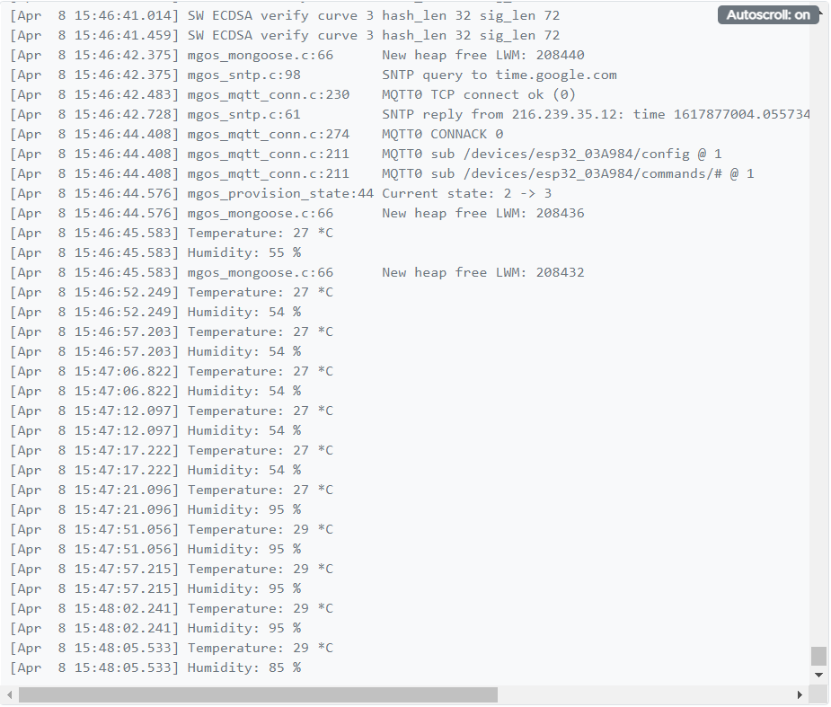
  • On successful upload, you should be able to start seeing the temperature and humidity values at the Serial Console of the MOS Tool.


RECEIVER ESP32 SETUP


  • Use the Mongoose OS Tool to upload the code below to the second ESP32 module. [P.S. Select the correct COM Port for the ESP32 module, if both the modules are connected to the same PC.]


load('api_timer.js');
load('api_dht.js');
load('api_config.js');
load('api_mqtt.js');
load('api_sys.js');
load('api_gpio.js')

// GPIO pin which has the built-in LED connected
let led = 2;
let topic = '/devices/' + Cfg.get('device.id') + '/config';

GPIO.set_mode(led, GPIO.MODE_OUTPUT);
GPIO.write(led, 0);

//Subscribe to the topic
MQTT.sub(topic, function(conn, topic, msg) {
  // print('Topic:', topic, 'message:', msg);
  //Parse the JSON message
  let obj = JSON.parse(msg);
  print('Temperature:', obj.temperature, '*C');
  print('Humidity:', obj.humidity, '%');
  //Turn the led on if temperature is greater than 30*C
  if(obj.temperature > 30){
    GPIO.write(led, 1);
  }
  else
    GPIO.write(led, 0);
}, null);


  • If everything was set up correctly, you should be able to receive the temperature and humidity values from the first ESP32 module and should be printed on the Serial Console. 

  • Also, if the temperature increases more than 30 degree celsius, the built-in LED of the module will turn on.