


SIM800 is a quad-band GSM/GPRS module that works on frequencies 850MHz GSM, 900MHz EGSM, 1800MHz DCS, and 1900MHz PCS .It also features GPRS multi-slot class 12/class 10 (optional), and supports CS-1, CS-2, CS-3, and CS-4 GPRS coding schemes. It has one UART port. It also has one USB port that can be used for updating firmware and for debugging. Audio channels are also there, which include a microphone input and a receiver output.SIM800 has one SIM card interface. It integrates TCP/IP protocol.SIM800 can be controlled/configured using simple AT commands. A host microcontroller can send AT commands over the UART interface and control the SIM800.
It can be used for sending/receiving messages, making calls, sending/receiving data over the internet, etc. This makes it useful for applications such as home automation, agriculture automation, etc.
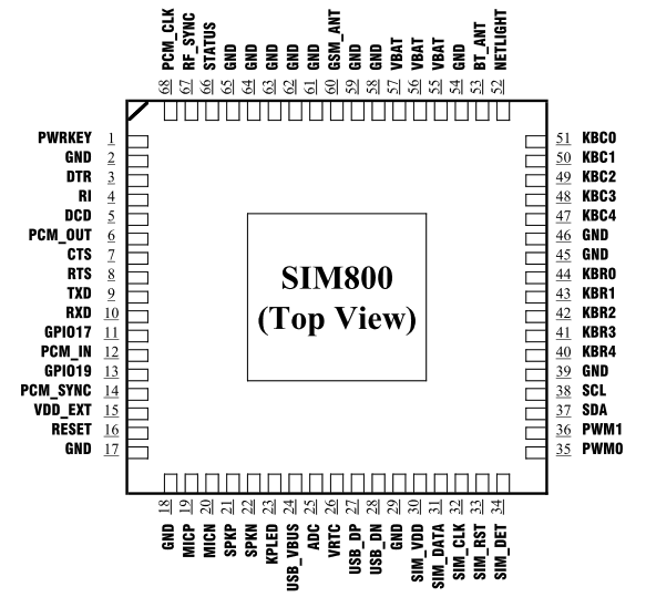
SIM800 Pin Diagram
Features
- Power supply: 3.4V ~4.4V
- Here used high current, high accuracy, low-dropout voltage regulator.
- Frequency bands: SIM800 Quad-band: GSM 850, EGSM 900, DCS 1800, PCS 1900. SIM800 can search the 4 frequency bands automatically. The frequency bands also can be set by AT command “AT+CBAND”.
- Transmitting power: Class 4 (2W):GSM850,EGSM900 , Class 1 (1W):DCS1800,PCS1900
- GPRS connectivity: GPRS multi-slot class 12(default)
Getting started
- Insert an unlocked SIM card to SIM card Holder. 6 Pin Holder for SIM Cards is provided on the Modem.
- Close SIM card Holder. Both 1.8 volts and 3.0 volts SIM Cards are supported by SIM800 – the SIM card voltage type is automatically detected.
- Assemble GSM Antenna to the modem
- Connect serial cable to the modem.
- Give power supply in between 4.5V to 12V through the power jack provided
- Default factory Baud rate is 9600
- When the modem is successfully powered-up, the Red LED on the modem (PWR) will be ON, the STS LED (BLUE) will light after 1-2 seconds and the NET LED(GREEN) will blink every second. After the Modem registers in the network (takes between 10-60 seconds), this LED will blink in step of 3 seconds.
LED status description:
The Network LED indicates the various status of GSM module eg. Power on, Network registration & GPRS connectivity. When the modem is powered up, this NETWORK LED will blink every second. After the Modem registers in the network (takes between 10-60 seconds), this LED will blink in step of 3 seconds. At this stage you can start using Modem for your application, showing that modem is registered with the network.
How to test
Check your GSM Modem Using Putty in PC:
- Before making connection with the system you should give external supply to the modem (4.5v-12v DC)
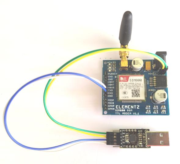
- For making a connection between GSM/GPRS TTL UART MODEM-SIM800 and PC you need CP2102 – TTL (5V) Converter.
Connections should be like below:
TX (modem)-RX (converter TTL)
RX (modem)-TX (converter TTL)
Make ground (GND-GND) and vcc (VCC-VCC) common
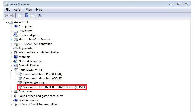
- Once you are done with all these procedures, choose the appropriate COM port that got assigned to the USB in your system by looking into the device manager like as shown below.
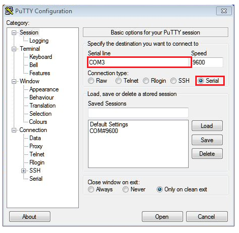
- Open putty terminal
- Figure out the COM port you’ll be using.
- Run Putty.
- Switch the Connection Type to Serial.
- Edit the Serial Line to match the COM port you want to use.
- Edit the Speed to match the BAUD Rate you want to use.
- Select the Open button to start the session.
- Now let’s try to check our Modem with AT commands for that we need to send following AT commands to Modem
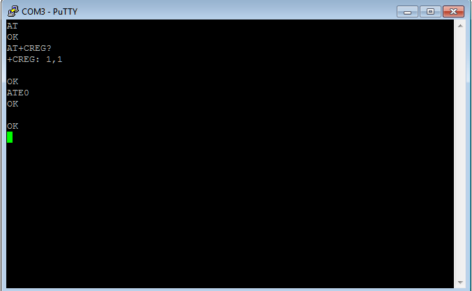
The above shown command: AT command (Followed by enter) after “OK” response, this signifies that our Modem is working properly.ATE0 command (Followed by enter) is being sent to stop the echo. AT+CREG? (Followed by enter) is being used to check whether the SIM got registered or not.
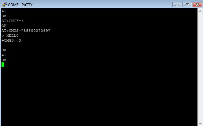
1. Sending a text message from SIM800 using AT Commands
Now next let’s send a message using GSM/GPRS TTL UART SIM800. For sending message we need to first send related AT commands to initialize the modem to send a message.
- The AT+CMGF=1 command (followed by enter) sets the GSM Modem in SMS text mode.
- AT+CMGS=<number>followed by enter gives<CR><write message><Ctrl+z>
<CR> represents the carriage return character.
<Ctrl+z>When you finish entering the SMS message body, you have to enter the <Ctrl+z> character to mark the end of the SMS message body.
+CMGS: x and OK; where x = “current number of sent SMS messages”
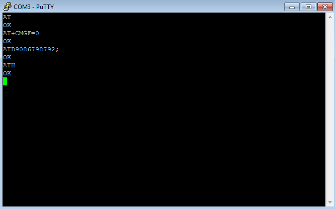
2. Call from SIM800 using AT commands
- The AT+CMGF=0 command (followed by enter) sets the GSM Modem in SMS text mode.
- To make a call type ATD<phone number>;
e.g.: ATD9086XXXXXX;
To disconnect the call type “ATD” & press enter. - If a call is coming to the GSM modem, a series of “RING” will appear on the window. If you want to connect to the call, then type “ATA” & press enter.
To get complete application note on AT commands click here
https://simcom.ee/documents/SIM800/SIM800_Hardware%20Design_V1.09.pdf
")
")


