


Here we will be seeing an example of wireless control of devices using RF technology. This system utilizes the RF module (Tx/Rx) for doing wireless controlling of devices, which could be used to drive an output from a distant place. RF module, as the name suggests, uses radio frequency to send signals. These signals are transmitted at a particular frequency and a baud rate. A receiver can receive these signals only if it is configured for that frequency.
A four channel encoder/decoder pair has also been used in this system. The input signals, at the transmitter side, are taken through two switches while the outputs are monitored on a set of two LEDs corresponding to each input switch. However upto 4 devices can be controlled using 4 switches with the modules used in the system.
The system can be used to control devices wirelessly using appropriate relays in the output side.
Components
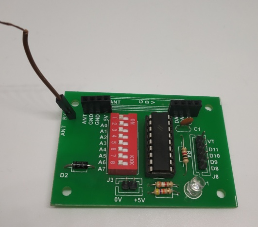
RF Encoder Module:
This module uses HT12E encoder IC. HT12E is an encoder integrated circuit of 2 12 series of encoders. They are paired with 2 12 series of decoders for use in remote control system applications. It is mainly used in interfacing RF and infrared circuits. The chosen pair of encoder/decoder should have same number of addresses and data format.
HT12E converts the parallel inputs into serial output. It encodes the 12 bit parallel data into serial for transmission through an RF transmitter. These 12 bits are divided into 8 address bits and 4 data bits.
HT12E has a transmission enable pin which is active low. When a trigger signal is received on TE pin, the programmed addresses/data are transmitted together with the header bits via an RF or an infrared transmission medium. HT12E begins a 4- word transmission cycle upon receipt of a transmission enable. This cycle is repeated as long as TE is kept low. As soon as TE returns to high, the encoder output completes its final cycle and then stops.
Specifications:
- Power Supply: +5V DC
- Enable pin: Active Low
- Number of inputs allowed: 4
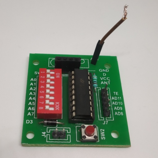
RF Decoder Module:
This module uses HT12D Decoder IC .HT12D IC comes from HolTek Company. HT12D is a decoder integrated circuit that belongs to 2 12 series of decoders. The chosen pair of encoder/decoder should have same number of addresses and data format.
In simple terms, HT12D converts the serial input into parallel outputs. It decodes the serial addresses and data received by, say, an RF receiver, into parallel data and sends them to output data pins. The serial input data is compared with the local addresses three times continuously. The input data code is decoded when no error or unmatched codes are found. A valid transmission in indicated by a high signal at VT pin. HT12D is capable of decoding 12 bits, of which 8 are address bits and 4 are data bits. The data on 4 bit latch type output pins remain unchanged until new is received.
Specifications:
- Power Supply: +5V DC
- Valid Transmission: VT pin High
- Maximum number of outputs: 4
RF Modules:
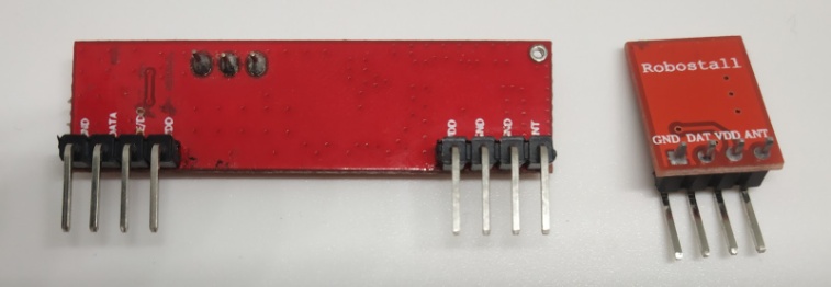
The RF module, as the name suggests, operates at Radio Frequency. The corresponding frequency range varies between 30 kHz & 300 GHz. In this RF system, the digital data is represented as variations in the amplitude of carrier wave. This kind of modulation is known as Amplitude Shift Keying (ASK).
Transmission through RF is better than IR (infrared) because of many reasons. Firstly, signals through RF can travel through larger distances making it suitable for long range applications. Also, while IR mostly operates in line-of-sight mode, RF signals can travel even when there is an obstruction between transmitter & receiver. Next, RF transmission is more strong and reliable than IR transmission. RF communication uses a specific frequency unlike IR signals which are affected by other IR emitting sources. This RF module comprises of an RF Transmitter and an RF Receiver. The transmitter/receiver (Tx/Rx) pair operates at a frequency of 434 MHz. An RF transmitter receives serial data and transmits it wirelessly through RF through its antenna connected at pin4. The transmission occurs at the rate of 1Kbps - 10Kbps. The transmitted data is received by an RF receiver operating at the same frequency as that of the transmitter. The RF module is often used along with a pair of encoder/decoder. The encoder is used for encoding parallel data for transmission feed while reception is decoded by a decoder. HT12E-HT12D, HT640-HT648, etc. are some commonly used encoder/decoder pair ICs.
Specifications:
- Range (Standard Conditions) : 100 Meters
- RX Receiver Frequency : 433 MHz
- RX Typical Sensitivity : 105 Dbm
- RX Supply Current : 3.5 mA
- RX IF Frequency : 1MHz
- RX Operating Voltage : 5V
- TX Frequency Range : 433.92 MHz
- TX Supply Voltage : 3V ~ 6V
- TX Out Put Power : 4 ~ 12 Dbm
Connection:
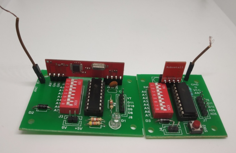
The Transmitter and Receiver modules are connected to the respective ports in the encoder and decoder module respectively as in the figure. Connect them by matching the names of pins in RF modules and Ports in Encoder and Decoder Modules.
Match all the dip switches in both modules for successful transmission.
Power both the modules using +5V DC supply.
Now do the wiring as in the below circuit diagram to control two leds remotely.
Circuit Diagram
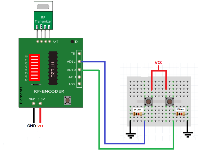
RF Encoder Module:
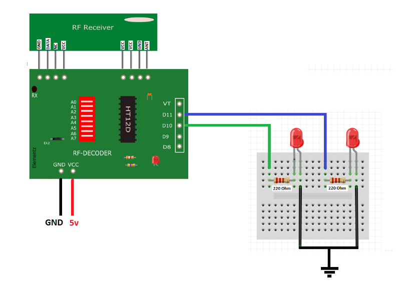
RF Decoder Module:
Working
This radio frequency (RF) transmission system employs Amplitude Shift Keying (ASK) with transmitter/receiver (Tx/Rx) pair operating at 434 MHz. The transmitter module takes serial input and transmits these signals through RF. The transmitted signals are received by the receiver module placed away from the source of transmission. The system allows one way communication between two nodes, namely, transmission and reception. The RF module has been used in conjunction with a set of four channel encoder/decoder ICs. Here HT12E & HT12D have been used as encoder and decoder respectively.
The encoder converts the parallel inputs (from the remote switches) serial set of signals. These signals are serially transferred through RF to the reception point. The decoder is used after the RF receiver to decode the serial format and retrieve the original signals as outputs. These outputs can be observed on corresponding LEDs.
Encoder IC (HT12E) receives parallel data in the form of address bits and control bits. The control signals from remote switches along with 8 address bits constitute a set of 12 parallel signals. The encoder HT12E encodes these parallel signals into serial bits.
Transmission is enabled by providing ground to TE pin which is active low. The control signals are given at pins AD11, AD10, AD9, AD8 of encoder module. The serial data is fed to the RF transmitter through DAT pin.
Transmitter, upon receiving serial data from encoder IC (HT12E), transmits it wirelessly to the RF receiver. The receiver, upon receiving these signals, sends them to the decoder IC (HT12D) through pin2. The serial data is received at the data pin (DIN) of HT12D. The decoder then retrieves the original parallel format from the received serial data.
When no signal is received at data pin of HT12D, it remains in standby mode and consumes very less current (less than 1μA) for a voltage of 5V. When signal is received by receiver, it is given to DIN pin (pin14) of HT12D. On reception of signal, oscillator of HT12D gets activated. IC HT12D then decodes the serial data and checks the address bits three times. If these bits match with the local address pins (pins 1-8) of HT12D, then it puts the data bits on its data pins (pins 10-13) and makes the VT pin high. An LED is internally to the connected to VT pin in the module. This LED works as an indicator to indicate a valid transmission. The corresponding output is thus generated at the data pins of decoder (D11,D10,D9,D7)
A signal is sent by making any or all the pins AD11,AD10,AD9,AD8 of encoder module high and corresponding signal is received at receiver’s end. Address bits are configured by using the dip switches of both encoder and decoder ICs. To send a particular signal, address bits must be same at encoder and decoder ICs. By configuring the address bits properly, a single RF transmitter can also be used to control different RF receivers of same frequency.
To summarize, on each transmission, 12 bits of data is transmitted consisting of 8 address bits and 4 data bits. The signal is received at receiver’s end which is then fed into decoder IC. If address bits get matched, decoder converts it into parallel data and the corresponding data bits get lowered which could be then used to drive the LEDs. The outputs from this system can be used to drive relays or other electronic devices that can operate on receiving a logic high.


