


RFID stands for radio frequency identification and it basically uses the radio waves to read the information on the tag. The RFID tags contains the embedded transmitter and receiver attached to an object. RFID is fast and does not require any contact between the reader and the tag and they can be read from feet’s away.
An RFID system consists of two parts: Tag and Reader
RFID Tag
An RFID tag contains a chip for storing information about physical object and an antenna to receive and transmit a signal. A RFID tag can usually store 1KB of data but it is enough for storing the name, credit card number, unique identification number, birth date and some more information.
RFID Reader
The RFID reader performs two functions: Transmit and receive. So you can also say it a transceiver. The RFID reader contains an antenna, radio frequency module and a control unit.
FEATURES
- Highly integrated analog circuitry to demodulate and decode responses.
- Supports ISO/IEC 14443 A/MIFARE.
- Typical operating distance in reading/Write mode up to 50 mm.
- Supports ISO/IEC 14443 A higher transfer speed communication up to 848 kBd.
- SPI up to 10 Mbit/s.
- FIFO buffer handles 64 bytes send and receive.
- Flexible interrupt modes.
- Power-down by software mode.
SPECIFICATIONS
- Frequency Range - 13.56 MHz ISM Band
- Host Interface - SPI / I2C / UART
- Operating Supply Voltage - 2.5 V to 3.3 V
- Max. Operating Current - 13-26mA
- Min. Current(Power down) - 10µA
- Logic Inputs - 5V Tolerant
- Read Range - 5 cm
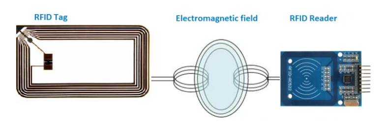
RFID WORKING
The RFID reader generates a high frequency electromagnetic field and when the tag comes near it, a voltage is induced in tags antenna coil due to induction. This induced voltage acts as power for the tag. The tag in return converts the signal in power and responds to the reader.
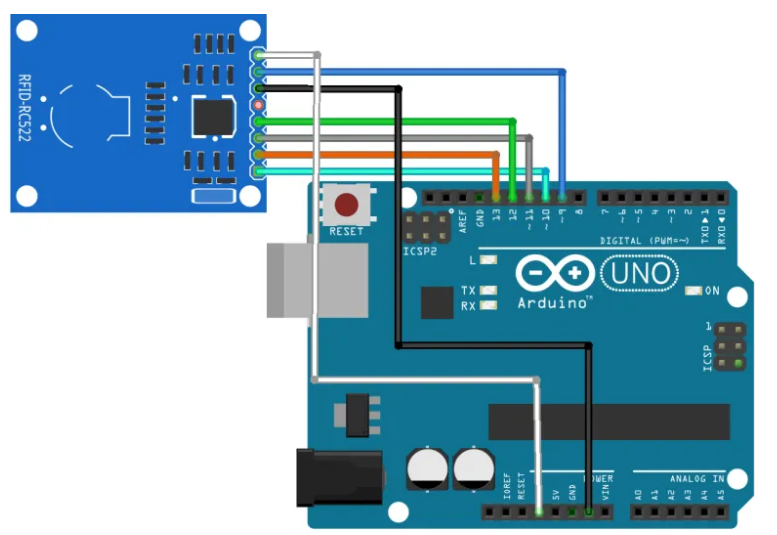
CONNECTION
| RFID-RC522 PIN | ARDUINO UNO PIN |
| SDA | 10 |
| SCK | 13 |
| MOSI | 11 |
| MISO | 12 |
| IRQ | UNUSED |
| GND | GND |
| RST | 9 |
| 3.3 V | 3.3 V |
LIBRARY
For making it easier to control the dot matrix, you need to download and install in your Arduino IDE the LedControl library. To install the library follow these steps:
METHOD 1
- Go to Sketch menu.
- Select Include Libraries.
- Go to Manage Libraries.
- Search for MFRC522 and install it.
METHOD 2
- You can install it externally using the following link : https://github.com/miguelbalboa/rfid
- After downloading the zip files,
- Go to Sketch → Include Library → Add .ZIP library
- Then add the downloaded zip files.
- Now the libraries are included in your Arduino IDE.
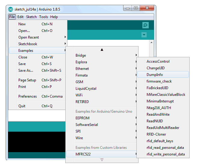
STEP 1
After Library installed, open the “Dumpinfo” from examples and upload it in your Arduino IDE.
STEP 2
Open two Arduino IDE window and Select Arduino UNO as Board and select the appropriate COM port.
Board: Tools > Board > Arduino/Geniuno UNO.

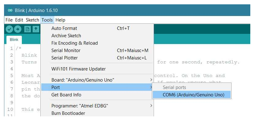
STEP 3
Select the serial device of the board from the Tools / Serial Port menu. This is likely to be COM3 or higher (COM1 and COM2 are usually reserved for hardware serial ports). To find out, you can disconnect your board and re-open the menu; the entry that disappears should be the Arduino board. Reconnect the board and select that serial port.
STEP 4
OUTPUT
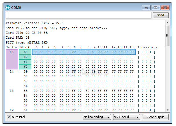
Upload the sketch and open the Serial Monitor. As soon as you bring the tag closer to the module, you’ll probably get something like the figure given below. Do not move the tag until all the information is displayed.
In this example project , it displays all the useful information about the tag including tag’s Unique ID (UID), the memory size and the whole 1K memory.The 1K memory of the Tag is organized in 16 sectors (from 0 to 15)Each sector is further devided in to 4 blocks (block 0 to 3).Each block can store 16 bytes of data (from 0 to 15).The Block 3 of each sector is called Sector Trailer and contains information called Access Bits to grant read and write access to remaining blocks in a sector. That means only the bottom 3 blocks (block 0, 1 & 2) of each sector are actually available for data storage, meaning we have 48 bytes per 64 byte sector available for our own use.Also The Block 0 of sector 0 is known as Manufacturer Block/Manufacturer Data contains the IC manufacturer data, and the Unique IDentifier (UID)
SAMPLE CODE:
The sample code is available from the git link here
Feel free to reach out to us at info@elementzonline.com for any product or tech related enquiries.
")
")


-500x500-250x250.jpg "RFID Tag Card 125kHz")
