


Here we will demonstrate how to interface the 8x8 LED matrix module with Arduino UNO while using the MAX7219 LED driver. The MAX7219 LED driver can be used to control 7-segment displays up to 8 digits, bar-graph displays, or 64 individual LEDs. The driver communicates with the Arduino through SPI so you only need three wires to control the display. Since the MAX7219 can control a maximum of 64 LEDs, the maximum size dot matrix display it can drive is 8×8 pixels. However, You can daisy chain multiple displays to create one large display by connecting DOUT of the first display to DIN of the next display. VCC, GND, CLK, and CS are shared between all of the displays. With an SPI interface, there is always one master device (the Arduino) that controls the peripheral devices (also known as slaves). You can control the display either through the Arduino’s AVR microcontroller hardware SPI interface or three arbitrary digital pins (software SPI). The hardware SPI pins (MOSI, MISO, and SCK) are at a specific location on each Arduino board. This interface is faster than using software SPI.
FEATURE
- Voltage Supply (Vs): 4.0V ~ 5.5V
- Supply current: 330Ma
- Segment drive source current: -40mA
- Shut down current: 150uA
- Scan rate: 500-1300Hz, 800Hz (typ.)
- Interface: SPI (four wire)
- Max serial clock: 10MHz (max)
- Operating temperature (MAX7219E): -40°C ~ 85°C [1]
CONNECTION
| MAX7219 Display | Arduino |
|---|---|
| VCC | 5V |
| GND | GND |
| DIN | 12 (MOSI) |
| CS | 10 (SS) |
| CLK | 11 (SCK) |
If you want to use software SPI instead, you can connect DIN, CS, and CLK to any of the digital pins of the Arduino. You just need to specify the pin numbers in the setup of the Arduino code.
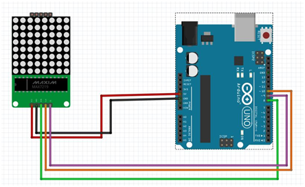
Circuit Diagram
LIBRARY
For making it easier to control the dot matrix, you need to download and install in your Arduino IDE the LedControl library. To install the library follow these steps:
METHOD 1
- Go to Sketch menu.
- Select Include Libraries.
- Go to Manage Libraries.
- Search for LedControl and install it.
METHOD 2
You can install it externally using the following link. https://github.com/wayoda/LedControl.
After downloading the zip files,
Go to Sketch → Include Library → Add .ZIP library
Then add the downloaded zip files.
Now the libraries are included in your Arduino IDE.
Adafruit library comes with really good examples for both 128x32 and 128x64 displays.
You will find examples of oled display under File > Examples >Adafruit SSD1306 > and then select the display type in the Arduino IDE.
The easiest way to display something on the dot matrix is by using the functions setLed(), setRow() or setColumn(). These functions allow you to control one single led, one row or one column at a time.
Here’s the parameters for each function
SetLed (addr, row, col, state)
addr: is the address of your matrix, for example, if you have just 1 matrix, the int addr will be zero.
row: Is the row where the led is located
col: Is the column where the led is located
state: It’s true or 1 if you want to turn the led on
It’s false or 0 if you want to switch it off
setRow (addr, row, value)
setCol (addr, column, value)
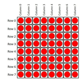
As previously stated, this matrix has 8 columns and 8 rows. Each one is indexed from 0 to 7. Here’s a figure for better understanding:
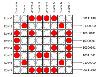
If you want to display something in the matrix, you just need to know if in a determined row or column, the LEDs that are on or off.
For example, if you want to display a happy face, here’s what you need to do:
SOURCE CODE
You can get the source code from our git
TESTING
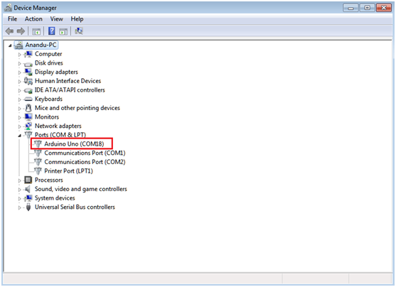
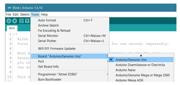
Open two Arduino IDE window and Select Arduino UNO as Board and select the appropriate COM port.
Board: Tools > Board > Arduino/Geniuno UNO.
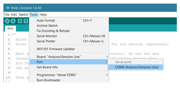
Port: Tools > Port in Arduino
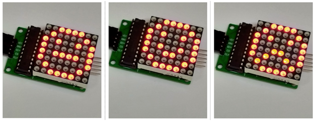
- Compile and upload the above given source code to your Arduino Uno board via Arduino IDE.
- After Done Uploading, you can see the output in the 8*8 Led Matrix Display
")
")


