


Starting up with SIM7600EI 4G LTE Modem V2.0
SIM7600EI 4G LTE modem provides enhanced connectivity and speed with 4G technology. This is one of the the most cutting-edge 4G LTE modules on the market right now. Without further ado, let's take a look.
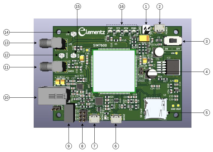
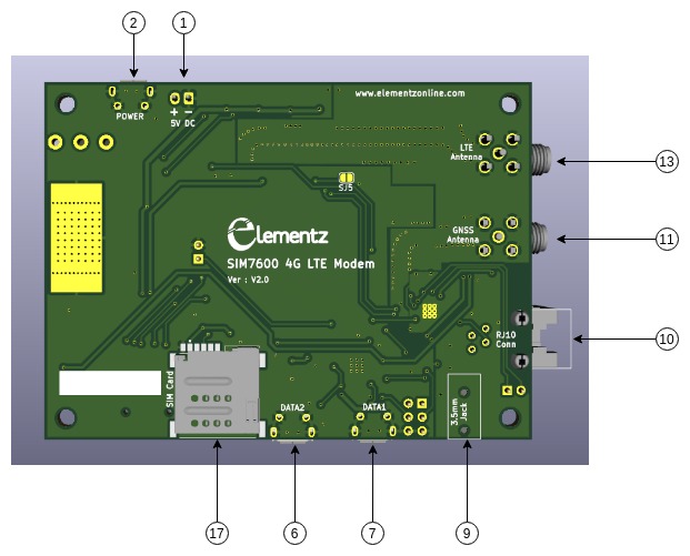
Pin Connections
1) JST Connector for 5V Power supply.
- Device works with 5V - 2 Amps DC Power supply. Polarity marked on Bottom side.
- Ensure correct polarity before powering on the device.
2) USB Connector for Power Supply - Preferred Method
- Device can be powered by 5V - 2 Amps Wall charger or Powerbank.
3) ON - OFF Sliding switch
-
ON - OFF Sliding switch for powering ON/OFF the device.
4) Powerkey Jumper
- Normally shorted to Ground with a Jumper Link.
5) SD Card Slot
- Use FAT32 formatted SD Cards. Maximum addressable capability is 32GB.
6) DATA2 USB Port
- USB interface compliant with the USB2.0 specification.
7) DATA1 USB Port
- USB Port of SiLabs CP2102 USB to UART converter.
8) TTL Jumpers for UART Interfacing
- UART TTL headers for interfacing with Arduino/ Raspberry Pi
9) 3.5mm HeadphoneJack
- For connecting Headphone with mic.
10) RJ10 Connector
- For connecting phone receiver.
11) GNSS SMA Connector
- For connecting GNSS SMA Antenna
12) GNSS UFL Connector
- For connecting GNSS UFL Antenna
13) LTE SMA Connector
- For connecting LTE SMA Antenna
14) LTE UFL Connector
- For connecting LTE UFL Antenna
15) Auxillary UFL Connector
- For connecting Auxillary Antenna (Optional)
16) LED Indications
- LED indications for PWR - Power, STS - Status, NTW - Network, Ring
17) SIM Card Socket
- Micro SIM Card Socket
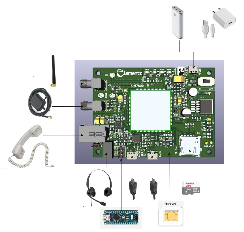
Hooking up the SIM7600 Modem
Power ON Sequence
-
Hook up everything as shown in above figure.
-
Slide the Sliding switch from OFF position to ON position.
-
PWR LED will turn ON instantaneously.
-
STS LED will turn on after some delay, it turns on when firmware inside the modem gets ready. Hence the delay.
-
Ring LED will turn ON and remain ON until activity such as receiving SMS or Voice call. If a call or SMS is in progress, it will blink or turn off.
-
NTW LED will blink if 2G/3G/4G network registered.
-
Avoid connecting antennas, SIM card, SD card etc while the device is powered. It may result in accidental short-circuit and damage the module.
Power Down Sequence
Proper Power Down will ensure longer life for the module. The following methods can be used to power off module.
- Power off module by AT command “AT+CPOF”.
- Over-voltage or under-voltage automatic power off. The voltage range can be set by AT command “AT+CPMVT”
- Power off module by pulling the PWRKEY pin down to ground. Power off Signal can be send from an MCU.
LED Indications
Power LED - PWR
- Turns ON after Sliding Switch in ON position.
Status LED - STS
- Turns ON when firmware is ready.
Network Status LED - NTW
| NTW LED Status | Module Status |
|---|---|
| Always On | Searching Network or Call Connecting(include VOLTE, SRLTE) |
| 200ms ON, 200ms OFF | Data Transmit or 4G registered |
| 800ms ON, 800ms OFF | 2G/3G registered network |
| OFF | Power off or Sleep |
Ring LED - RING
- Ring LED will be ON until activity such as receiving SMS or Voice call.
DATA1 LED - D9
- Turns On when micro USB cable is connected & CP2102 turns ON.
Interfacing with Arduino (or any MCU)
For TTL UART interfacing, remove the Jumper short links and connect as shown in figure. (adjacent to label TXD, RXD)
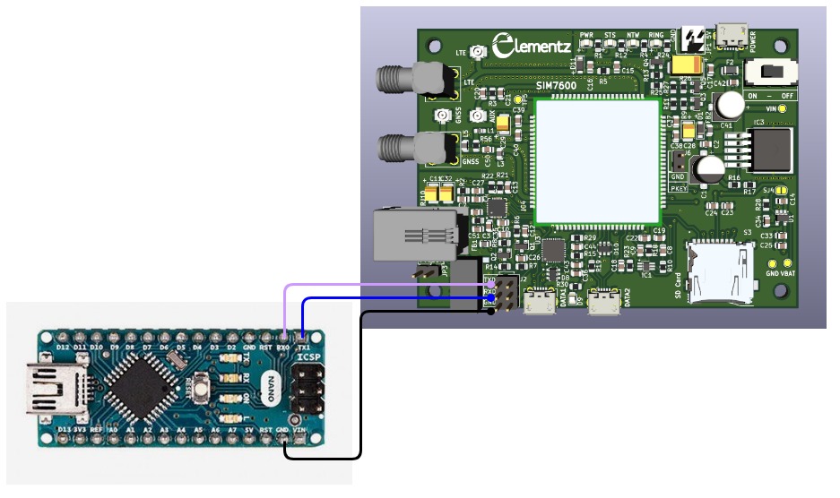
When Jumper short links are removed, data will not arrive at DATA1 USB port.
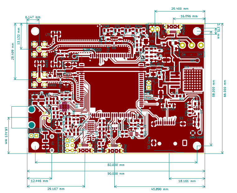
Dimensions
Product Page : https://www.elementzonline.com/sim7600e-4g-gsm-ttl-usb-modem-with-sma-antenna?search=7600&description=true
More information can be found on our Wiki.
Important Links :
FAQ
1. I am using PuTTY terminal emulator but I am not able to type 'AT' in the putty window.
Try another terminal emulator like Hterm if you are using windows. (GTK term for linux).
P.S - Make sure to select : CR - LF when transmitting and press enter. (Carriage return and New line (\n & \r))
http://der-hammer.info/pages/
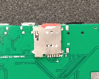
2. What is the orientation of inserting SIM card?
Insert the SIM card as shown in below image. SIM card socket is springloaded, so a click sound can be heard when it is properly inserted.
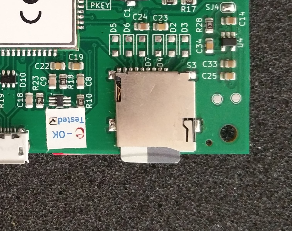
3. What is the orientation of inserting SD card?
Insert the SD card as shown in below image. SD card socket is springloaded, so a click sound can be heard when it is properly inserted.
4. NTW LED is always ON and not blinking. I received 'CME ERROR SIM NOT INSERTED'
Check SIM card and antenna is properly connected. Try checking with another SIM card.


")
")
2 Comment(s)
hi,
using this can we recieve and make calls from windows pc?
-nitin s
hello
can i use it for sending video for a lorge distance 400 m
Leave a Comment