


Hi Readers,
This is my post after 1 year of domain change. Now the good news is I am back home to develop more on Hardware technologies. This post is intended to give some insights on LoRa technology for long distance communication by experimental tuning of parameters for maximizing the signal reception range.
Lora is a wireless technology which enables the things(Internet of Things) to communicate over long distances without any repeaters. The long distances are in the order of kilometres!!
This guide is presented to the readers as an attempt to describe the various factors that affect the overall range when using LoRa modulation scheme.
Hardware used:
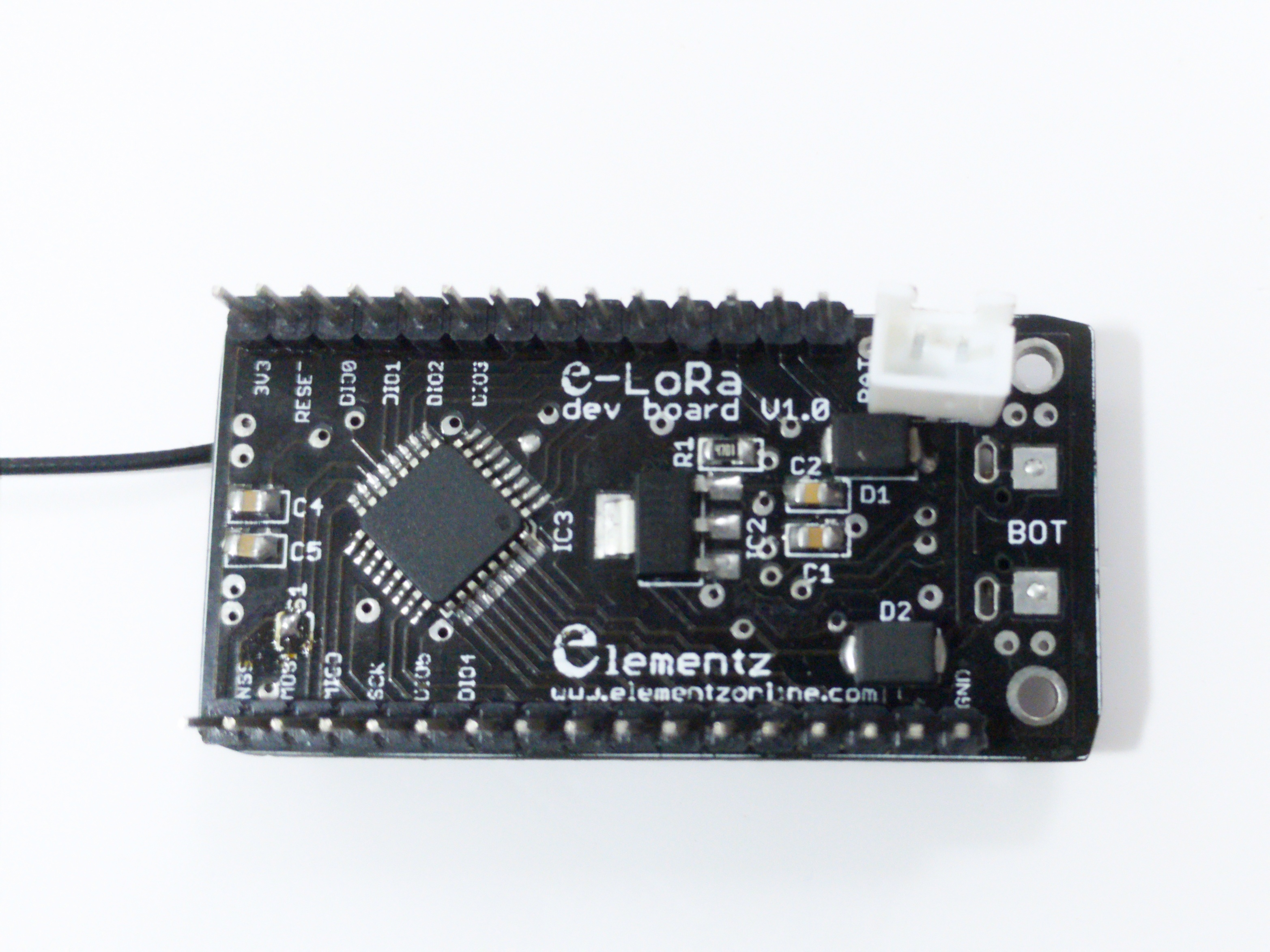
- Arduino-LoRa – Ra-02 – SX1278 based transceiver.
It's an FSK/OOK, LoRa module
Factors affecting range
- Transmitting power
- Antenna parameters
- Spread spectrum
- Bandwidth
Quality Factors
- Directional antenna
- Coding Rate
When selecting wireless transceiver, the first and foremost thing that comes to our mind is the maximum range attainable, especially for low bitrate applications. In order to increase range in many existing solutions, we require repeaters, mesh topology, or use high gain massive antennas. But all of them are costly solutions and also most are restrictive by law because of the transmission power limitation imposed on our country. Another issue is that for attaining high gains and transmission power, the transmitters require more power, which requires a massive battery. LoRa is a proprietary wireless protocol developed by Semtech for sending data to orders of kilometres, with extremely low power requirement. This accounts for the introduction of the Internet of Things implementation using the LoRa technology.
As an R&D organisation, we at Elementz made an effort to estimate the maximum range attainable on urban areas. The test was conducted at the heart of Trivandrum City, Kerala, India. This is a non-metro city, but the urbanization caused the raising of huge buildings. Our company having one of our offices at Trivandrum was the central point of testing. We used two LoRA Ra-02 modules to carry out the experimentation, where one of the module acts as the receiver and other as a transmitter.
We have developed an Arduino compatible hardware to communicate to the LoRa chip which can be bought from our store(Product Link: https://www.elementzonline.com/Elementz-Arduino-LoRA-RA-02-AI-Tinker-WIRELESS-TRANSCEIVER-SX1278). This module which has builtin user led was very helpful in carrying out test. Once again Arduino Ecosystem come to the rescue on reducing the development time.
About firmware:
We used the GitHub repository from Mr. Sandeep Mistry to get started(Special thanks to him). This Arduino library covers almost all the functionality related to the LoRa mode in the Ra-02 module. We tweaked the library a bit. The source is uploaded to our Git repository.
How we extended range:
Note: The values that we have chosen below are the best we could manage to get in terms of maximum range. More tuning may increase the signal quality or range further.
- 1) Spread Factor
From the datasheet, its mentioned that the supported value is between 6 and 12. Different values of the spread spectrum make the transmitted signal orthogonal. So it's important to choose the same Spread Factor for both the receiver and transmitter. We chose 12 as the optimum value as the maximum transmission power is attainable at that SF value(+17 dB). Also, more symbols are used for transmission (2SF). The adverse effect of choosing large value is that it will take more time to traverse.
In India we have a free band at 433-434 MHz, which comes under Band 2. We tuned the Radios to 433 MHz band.
- 2) Signal Bandwidth
This choice was a quite tricky one. As RA-02 is a low-cost LoRa compatible board which has cheap assembly components, we cannot expect crystal accuracy to be good enough to narrow our bandwidth. But theoretically the low signal bandwidth should be giving more range. Also these crystals will be having some frequency deviation when temperature changes. Our chips didn’t communicate to each other as expected in the low signal bandwidth settings ie. 7.8KHz. So we choose an intermediate value available which is 62.8KHz. We were able to get good reception under this setting.
- 3) Coding Rate:
The default coding rate is 4/5 indicates 5 bits are used for sending when we send a nibble(4 bits) as payload. We chose 4/8 which helped to recover the payload correctly, especially on long distances.
- 4) Antenna used
We couldn’t get a tuned antenna at 433 MHz, which may have improved the range a lot. We used a more generic antenna, which gives -35 dB RSSI value when the modules were close enough, which is not so bad.
- 5) Transmission power
This value is not required to be experimented as the higher value will definitely increase the range. Thus we choose +17dB which is the maximum possible value.
Ranges obtained:
The maximum range we obtain in Urban area is about 1 kilometre. The receiver is placed in open space outside our office building. The transmitter was moved away from the receiver and the RSSI and SNR values are logged in the receiver side. The data recovery seems to be good as we didn’t receive any faulty packets with 4/8 Coding rate. Previously we used 4/5 coding rate which gave many corrupted data in the payload which is received.
More hacking news coming soon. Stay tuned...
Please use the comment section to send the feedback. Happy Hacking !!
Important Links
- Transmitter and Receiver code - https://gitlab.com/elementzonline/Arduino-Sample-Codes/tree/master/LoRa_RangeTest
- SX1278 datasheet - https://cdn-shop.adafruit.com/product-files/3179/sx1276_77_78_79.pdf
- Elementz Lora Product page - https://www.elementzonline.com/Elementz-Arduino-LoRA-RA-02-AI-Tinker-WIRELESS-TRANSCEIVER-SX1278

